EUNICE – Eco-design and Validation of In-Wheel Concept for Electric Vehicles (December 2014 / January 2015)
- Website: http://www.eunice-project.eu
Motivation and Objectives
The main objective of this project is the design, development and validation of a complete in wheel motor assembly prototype (electric motor, power electronics, reduction gear, structural parts and wheel), based on a McPherson corner suspension topology, to meet typical “B segment” electric vehicle requirements.
The main technical risks associated with the use of an in-wheel concept are the temperatures achieve under extreme operation conditions, vehicle dynamics, driveability, safety and durability. The proposed baseline concept is based on an air cooled motor in wheel concept, with conventional airflow driven by vehicle, and assisted by an innovative wheel design.
Technical Approach
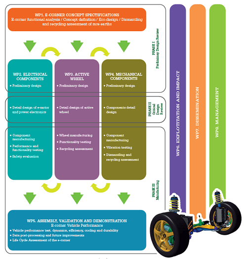
The project is structured in work packages addressing the different development steps:
Key achievements
WP1 – E-Corner Specifications
In this WP the specifications and performance criteria for the EUNICE solution are defined, oriented to a B-segment type vehicle. Functional analysis of each of the sub-modules that integrates the e-corner is performed, in order to define the basic requirements for their design. Eco-guide lines?
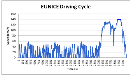
Figure 1. Representation of EUNICE Driving Cycle (speed vs. time), limited to 140km/h of maximum speed.
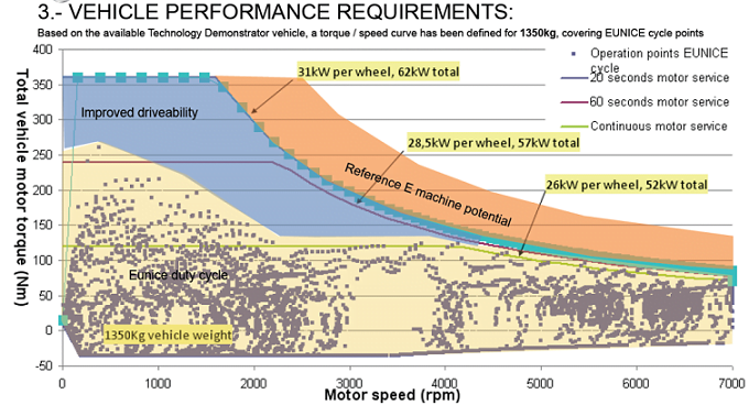
Figure 2. Electric motor speed/torque diagram for motor Baseline design with driving cycle requirements.

WP2 – Electrical components
Design, development and manufacturing of the electrical components of the e-corner are carried out in this WP: the e-motor, and power electronics, together with their related sub-systems such as cooling system and safety system. These components are being designed, manufactured and evaluated. High torque density axial flux electric motors are used in order to provide high torque and large cooling area. Their design will follow the eco-design guidelines.
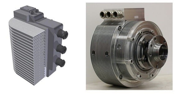
Figure 3. (Left) Final design of the inverter by INFINEON. (Right) Axial Flux Permanent Magnet Electric Motor designed by GKN Evo and integration with reduction gear by GKN Driveline.
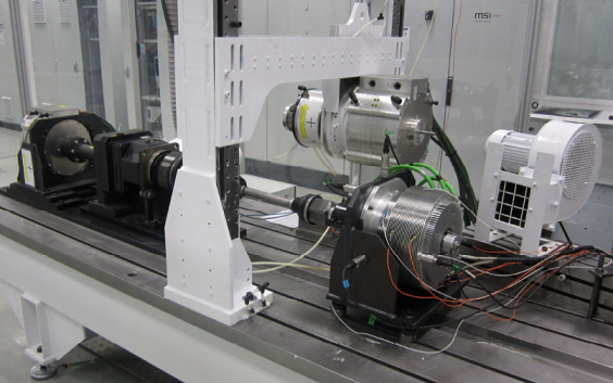
Figure 4. EUNICE e-drive test and validation phase activities.
WP3 – Active wheel
In this WP, an innovative design of the wheel is developed to accommodate the components of the e-corner and to improve heat evacuation of whole assembly. New manufacturing processes have been evaluated in order to reduce the weight of the solution.
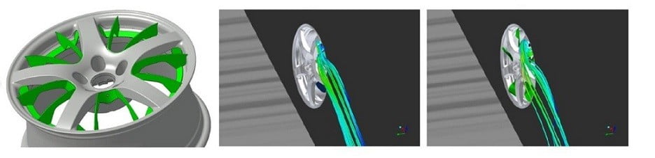
Figure 5. (Left) Active wheel with twisted blades to improve the salient air flow. (Centre) Wheel CFD simulation without blades. (Right) Wheel CFD simulation with blades.
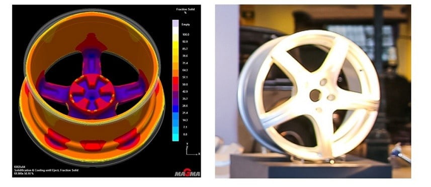
Figure 6. (Left) CAE process simulation of the wheel rim. (Right) Wheel rim initial prototype.

WP4 – Mechanical components
A complete suspension system has been developed to provide adequate driveability characteristics of urban “B segment” cars, reducing weight and providing adequate space for the integration of the complete motor in wheel solution. Novel components such as knuckle, subframe and control arms have been developed.
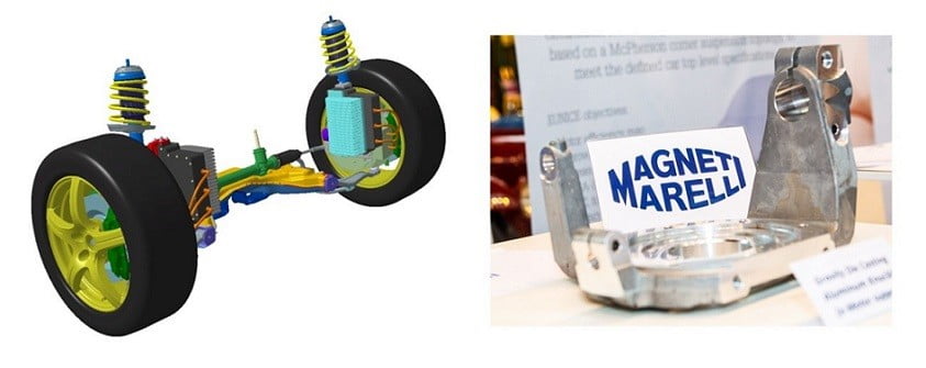
Figure 7. (Left) Complete front axle CAD model. (Right) Knuckle prototype.

WP5 – Assembly, validation and demonstration
Integration of the EUNICE solution into a demonstrator vehicle will be carried out in this WP. This stage involves the execution of the necessary tests in order to demonstrate the feasibility of the solution from both functional and subjective driving point of view. These validation tests are representative and will cover the most important operational aspects that the EUNICE solution will address, once operating as the power drive of a vehicle.
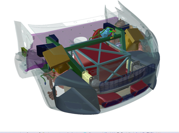
Figure 8. Design of demonstrator car based on existing vehicle representative of B segment, with battery located at engine bay.
WP6 – Exploitation and impact
Exploitation plan is defined for the industrialization of the project results and to assess the technological impact of the project developments by the consortium. Based on inputs from interviewed OEM´s, the potential design derivatives of Eunice solution are being identified and their feasibility assessed.
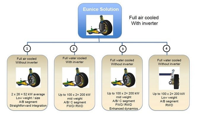
Figure 9. Eunice derivative designs for other vehicle types.
WP7 – Dissemination
Dissemination activities are carried out to make stakeholders aware of Eunice technology, research results and the potential applications on future electric vehicles. (TRA2014, EVS27, E-Mobility Event, EEVC 2014).
Specifications have been reviewed by different OEM to provide input in order to increase project impact.
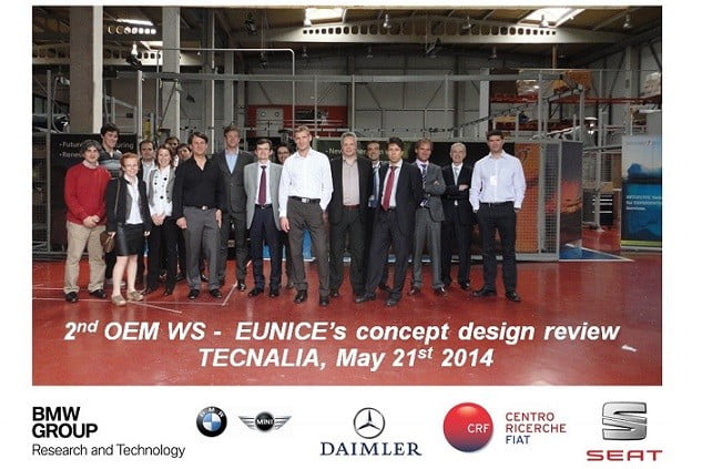
Figure 10. OEM workshop held in Tecnalia (May 2014). OEM´s external to the project are invited regularly for specification and design review.

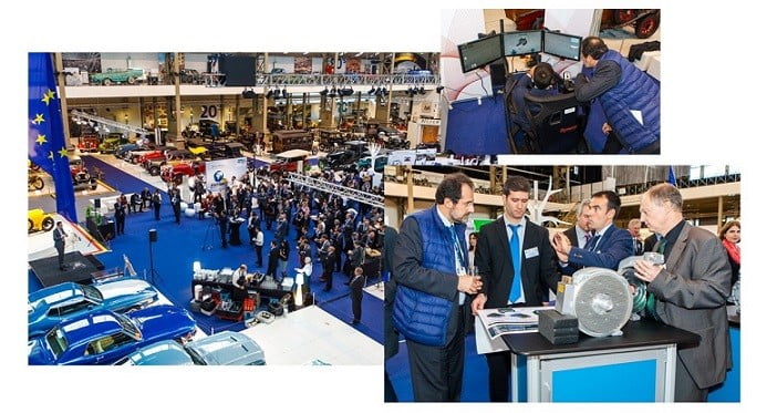
Figure 11. Eunice presentation in E-Mobility event held in Brussels (Nov 2014).

Organizational Information
Budget: 4.845M€
Funding: 2.9M€
Duration: 36 Months
Start: September 2012
Grant agreement no: SCP1 – GA – 2012 – 285688
Coordinator: Alberto Peña – TECNALIA
Partners: TECNALIA, PIninfarina, GKN Evo, GKN Driveline, Infineon, Magnetti Marelli, Hayes Lemmerz, AIT, AIC, IVL, CIE Automotive, Clepa, Denn.